
EMBEDDED NOTES · OPEN-SOURCE
An Explosive Embedded Project on GitHub: ESP32-C3-Based Capacitor Explosion Alarm Clock
Ordinary alarm clocks wake people up with buzzers, music, or vibrations. But a GitHub project called capacitor-alarm-clock takes a very different approach: when the alarm goes off, the circuit subjects electrolytic capacitors to abnormal electrical conditions, producing a loud bang to wake someone up. The GitHub repository describes the idea rather bluntly: “capacitor blow up, human wake up.” The creator openly admits that it’s an elaborate joke that required a lot of effort, and explicitly warns that capacitor explosions can be quite violent and that the resulting fumes are unsafe to inhale. In other words, this is not an alarm clock you should try to replicate or keep running on your bedside table.
GitHub Repository:
https://github.com/ArcaEge/capacitor-alarm-clock
Safety Notice
Exploding electrolytic capacitors can produce high-velocity fragments, hot materials, and irritating fumes. This article is intended to introduce an open-source engineering project. Building this device or conducting similar experiments indoors or near a bed is strongly discouraged.

Putting the dangerous gimmick aside, this is actually a surprisingly complete project. It includes a full PCB design, bill of materials (BOM), 3D enclosure models, PlatformIO firmware, and a web-based configuration interface. The repository currently has around 117 GitHub stars.
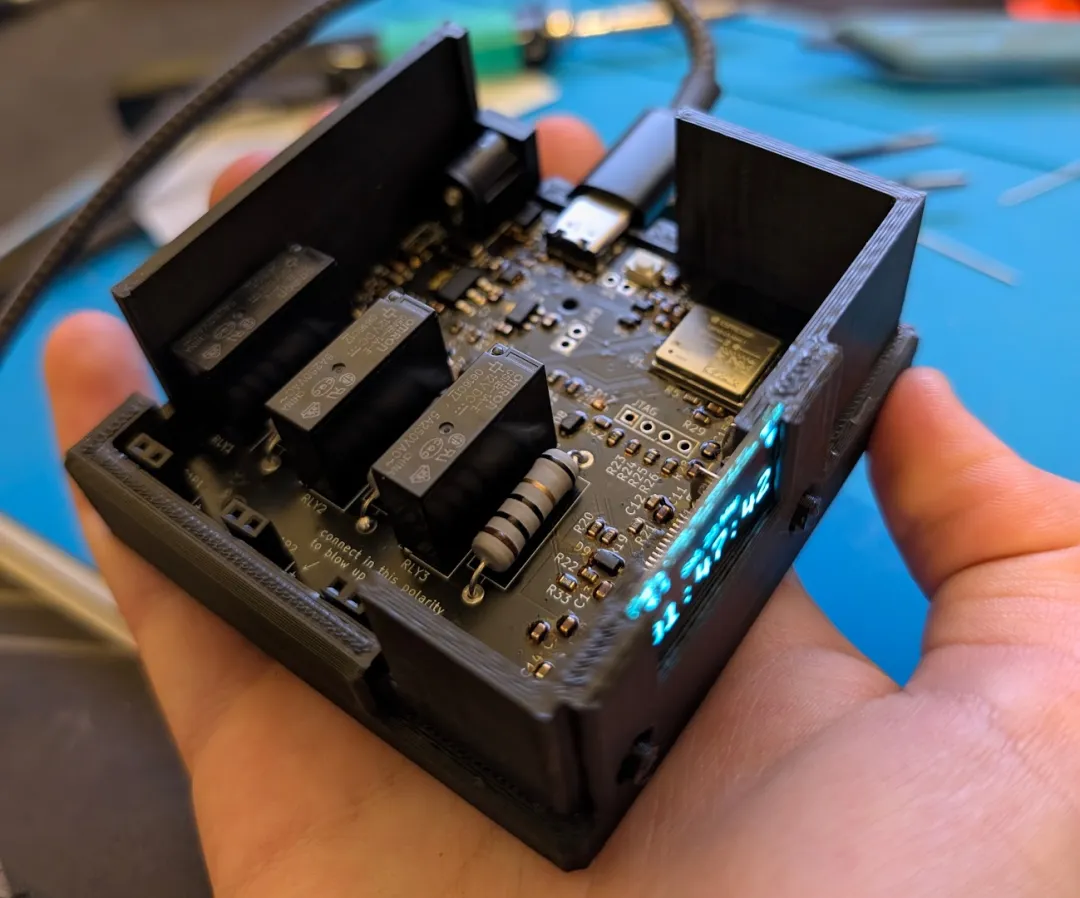
The entire device measures just 72 × 74 × 36 mm. On the front, there’s a 128 × 64 OLED display and two buttons, while the top has three capacitor slots. Inside is a three-channel, high-side switching circuit controlled by an ESP32-C3. From the outside, it looks like a perfectly ordinary little alarm clock. Remove the cover, though, and the relays, current-limiting resistors, and wide PCB traces make it immediately clear that this is no ordinary clock.
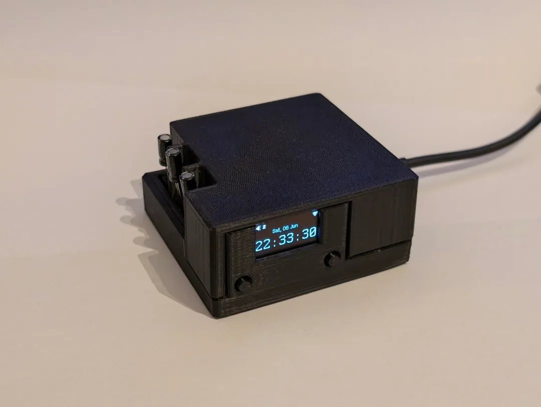
The front panel features only an OLED display and two buttons, giving the device a remarkably understated appearance.
The Hardware Isn’t Complicated, but Every Component Has a Purpose
The main controller is an ESP32-C3-MINI-1-N4, featuring a RISC-V core and built-in Wi-Fi. It handles network connectivity, NTP time synchronization, menu interaction, alarm scheduling, and web-based configuration.
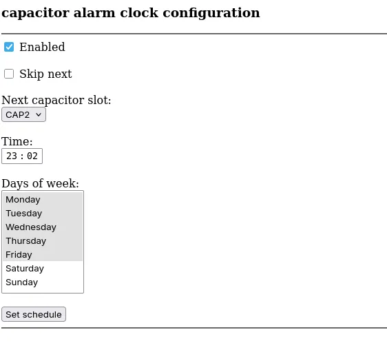
The display is an X096-2864KSWPG01-H30 OLED module with an SSD1315-compatible controller and a resolution of 128 × 64 pixels. Users can navigate the settings using the left and right buttons and combinations of both buttons. They can set the alarm time, recurrence schedule, and capacitor slot to be used for the next alarm. Once the device is connected to the local network, its configuration page can also be accessed through its IP address.
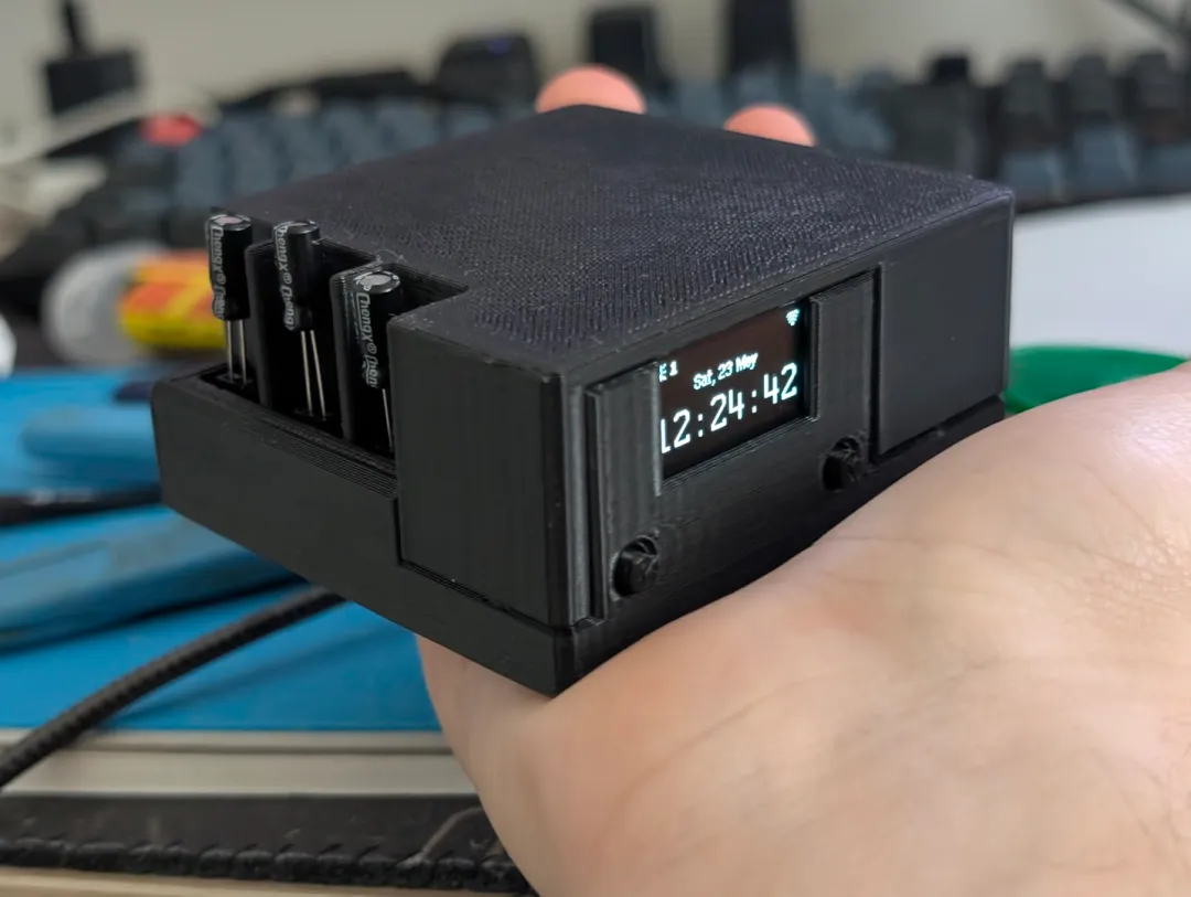
The really unusual part is the three relay channels. According to the BOM, the project uses three Omron G5NB-1A-E DC12 relays. Each channel also includes a BC817 transistor, an indicator LED, a Schottky diode, and a high-power series resistor.
The relays separate the ESP32-C3’s low-voltage control logic from the actuator side, while the series resistors limit fault current. The repository documentation specifies an upper limit of approximately 3 A, partly to prevent a shorted capacitor from overwhelming the power supply.
Power can be supplied through USB-C or a 12–15 V DC barrel connector. Onboard linear regulators then generate the 12 V and 3.3 V supply rails. The creator also acknowledges that stepping down a relatively high input voltage using linear regulators generates considerable heat. If the hardware were redesigned, a buck DC-DC converter would be a more sensible choice.
Main Components
| Component | Function |
|---|---|
| ESP32-C3-MINI-1-N4 | Main controller, Wi-Fi connectivity, NTP time synchronization, and web-based configuration |
| 128 × 64 OLED | Displays the time, menus, and device information |
| G5NB-1A-E DC12 × 3 | Relays for the three output channels |
| BC817, Schottky diodes | Relay driving and inductive load protection |
| USB-C, 12–15 V DC input | Power supply and debugging connection |
| 12 V / 3.3 V linear regulators | Relay and logic power supplies |
The Actuator Design Is Completely Absurd
The firmware is built using PlatformIO. Early in the project, while the developer was still waiting for ESP32 components to arrive, an ESP8266 build target was also retained.
After powering on and connecting to Wi-Fi, the device synchronizes its clock through NTP and displays the current time on the OLED. The two buttons handle menu navigation and confirmation through button combinations, while the web server provides another, more intuitive configuration interface.
From a software architecture perspective, this isn’t particularly different from an ordinary internet-connected clock. The time service handles synchronization, the configuration module stores alarm schedules, the display task updates the user interface, and the trigger module selects an output channel when the specified conditions are met.
The absurd part is simply that the final “output channel” isn’t connected to a buzzer. Instead, it drives three sets of relays.
This design also exposes a very typical embedded systems problem: network time synchronization does not automatically make an alarm clock reliable.
A disconnected Wi-Fi connection, an unavailable NTP server, or a device reboot before time synchronization can all affect when the alarm is triggered.
If someone wanted to turn this into a safe version, they could retain the OLED, web configuration interface, and three output channels, but replace the dangerous loads with a buzzer, vibration motor, and high-brightness LED. Adding a real-time clock (RTC) and a backup battery would further improve reliability.
This approach would preserve the most interesting parts of the project’s software architecture without requiring anyone to deal with electrolyte, flying fragments, or irritating fumes inside their room.
The PCB and Mechanical Design Are Where This Joke Gets Surprisingly Serious
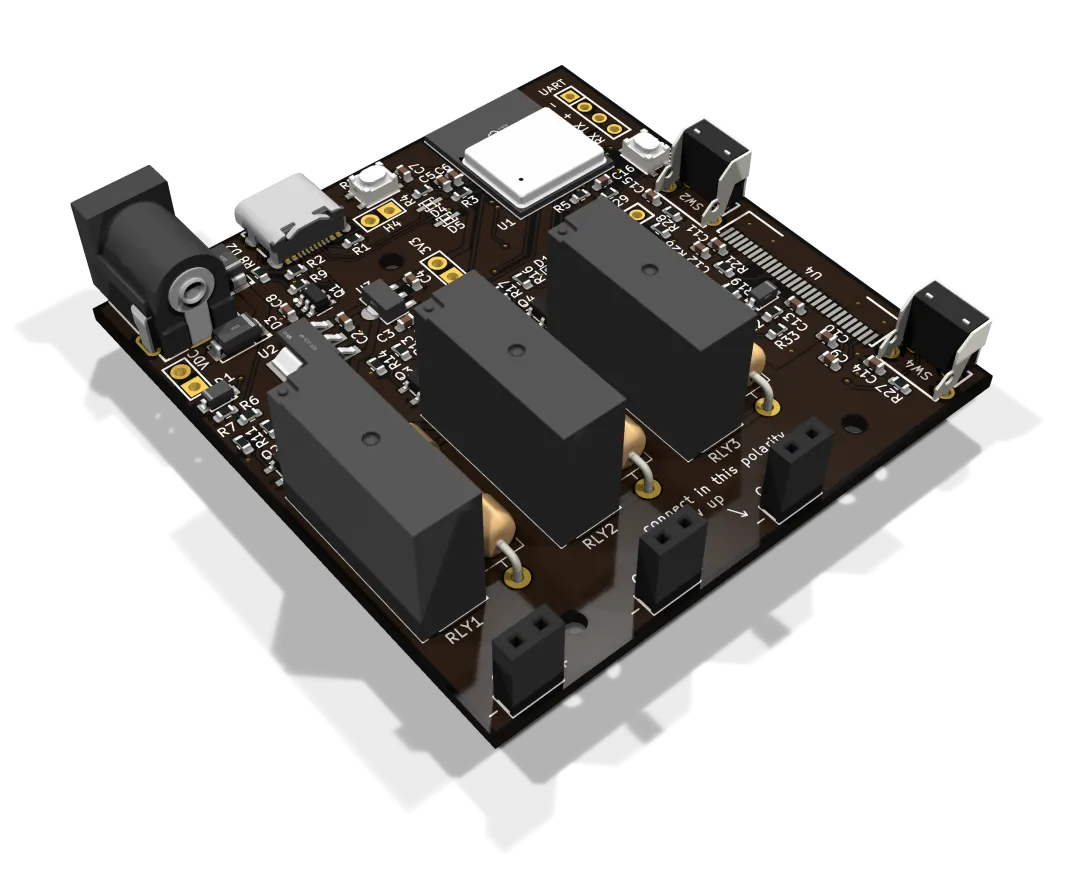
The repository organizes its KiCad project into hierarchical schematics covering the main board, ESP32, power supply, USB interface, relays, and display circuitry. It also provides Gerber files, a component BOM, enclosure CAD files, and an Onshape project.
Based on the general component cost estimate, the PCB costs approximately $2, while the onboard components cost around $20. Add a few screws and miscellaneous consumables, and the overall cost is still fairly reasonable.
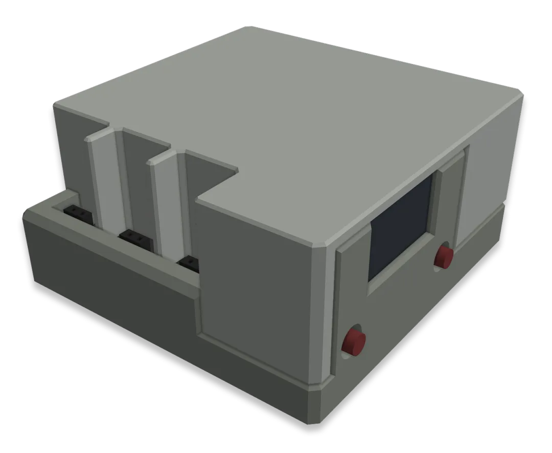
The enclosure consists of an upper and lower shell. Three openings on the top correspond to the capacitor slots, while the OLED and buttons are mounted on the front panel. The PCB occupies almost all of the available internal space.
And that’s what makes this project worth examining. The creator didn’t stop at a breadboard demonstration. Instead, they took a ridiculous idea all the way through schematic design, PCB layout, firmware development, mechanical design, and assembly validation.
The engineering files are sufficiently complete and the naming conventions are relatively clear, making the project a useful reference for learning about ESP32-C3 minimal system design, USB-C power supply circuitry, relay driving, NTP time synchronization, and lightweight web-based configuration interfaces.
As for the loud bang that made this project famous, watching the demonstration is more than enough. If you actually want to build something similar, it’s better to replace all three loads with safe actuators right from the beginning.
There are plenty of ways to wake someone up. There’s really no reason for an alarm clock to double as a fire drill.
Discussion